분석 서비스 > CP 소개
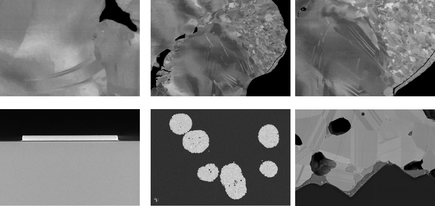
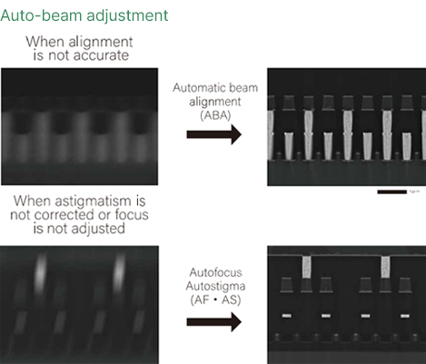
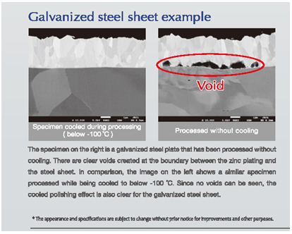 아연(Zn)이 도금된 강판에서의 예시이며 냉각 방식의 밀링 여부에 따른 결과를 비교하고 있습니다.
아연(Zn)이 도금된 강판에서의 예시이며 냉각 방식의 밀링 여부에 따른 결과를 비교하고 있습니다.
아연(Zn)이 도금된 강판에서의 예시이며 냉각 방식의 밀링 여부에 따른 결과를 비교하고 있습니다. 
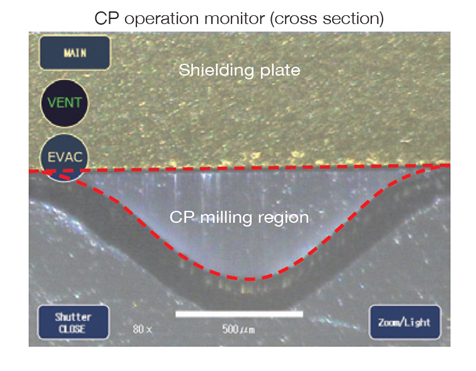
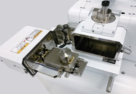
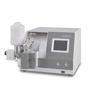
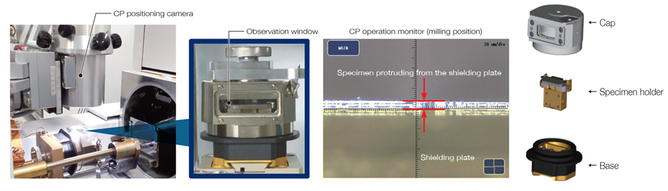
The milling position can be checked and adjusted by observation through the window of the transfer vessel.
The milling position can be checked and adjusted by observation through the window of the transfer vessel.